
![]()
 |
|
|
|
|
Intusoft Newsletter Issue
#44, November 1995
Copyright ©2002
Intusoft, All Rights Reserved
At Wescon/95, Intusoft will be introducing a new and unique SPICE modeling product called SALT or SPICE Array Linking Technology. Major upgrades to ICAP/4 for bothWindows and the Power Macintosh product lines will also be previewed. (Booth 6671).
SALT is an HDL modeling methodology that uses OLE2 to6Transient Suppression add functionality that is not possible with traditional modeling techniques. For example, SALT enables ISSPICE to link with various hardware data acquisition boards. This is a MAJOR NEW feature, one not offered by any other EDA vendor. The impact on hardware test and breadboarding promises to be significant. With SALT, you could use your test bench to create real world stimulus for a simulation, or use ISSPICE to generate test waveforms using a simulation of a circuit too expensive to build on the bench. The possibilities for connecting SPICE to the real world are endless. At Wescon/95 Intusoft will demonstrate a unique “Virtual Test Bench” consisting of ISSPICE4 and National Instruments™ Daq and output boards.
The SALT kit also provides a number of functions including array processing algorithms, transforms (wavelet), FFTs, matrix math, hardware input and output, file input and output, and the capability to link OLE2 models to ISSPICE. Source code for these functions is included with SALT so that you can easily develop and debug your own interfaces. The price of SALT is $495 and it will be released in the 1st quarter of 1996. If you weren’t able to attend Wescon feel free to use the attached bingo card, or contact your local dealer, for more information.
At Wescon, Intusoft will be showing the latest version of its popular Windows based ICAP/4 simulation system. The schematic entry program included with ICAP/4, called SpiceNet, has been updated with new PCB layout interfaces, more support for mixed mode circuits, an Orcad™ symbol/ schematic translator, streamlined symbol creation for subcircuit netlists and symbols, and a Monte Carlo Wizard. The revised symbol editor contains a Symbol Wizard that makes creating symbols painless. Users will be allowed to import symbol artwork via the clipboard and utilize Windows meta-files, resulting in superior looking schematics.
Another unique schematic feature is the ability to handle mixed-technology or complex electrical designs via a multilayer structure. A schematic can include electrical, mechanical, or mathematical objects, artwork, or connections to laboratory test equipment. Schematic objects can then be mixed on different layers to create various simulation scenarios. Users can specify which layers to view, edit, print and simulate. This allows different levels of hierarchy, complexity and connectivity to be easily manipulated.
The new ICAP/4 system includes thousands of new digital, analog, and sampled-data models. Users can even “plug in” system level blocks like FIR and IIR filters, complex state machines and mathematical transfer functions, and simulate them along with traditional electrical elements. While ISSPICE4 is best known for its electrical circuit simulation capabilities, these new features allow you to mix mathematical, mechanical, hydraulic, thermal, and physical systems all in the same simulation.
A new interactive on-line help system provides users with extensive SPICE syntax and problem solving help. The help is not simply a text listing, but a true interactive environment where questions are answered with movies, sounds, and graphics. Rather than simply displaying instructions or providing a separate tutorial, the movies actually show the user how to perform a task. The price for the new ICAP/4 version is undetermined, but will be available in the 1st quarter of 1996.
Microsim’s decision to abandon
the Macintosh market has left only one major EDA vendor, Intusoft,
to fill the simulation tool void. Intusoft is dedicated not only
to maintaining its Macintosh line-up, but improving it as well.
Intusoft will be showing its new optimized SPICE for the Power
Macintosh 601 and 604 processors at Wescon. The new ISSPICE4 program
boasts a speed increase of more than 100% over previous versions.
For some circuits, this means superior performance to Pentiums
of the same clock speed. An
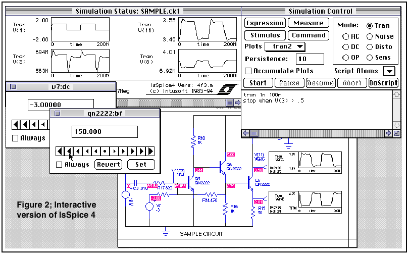
interactive version (Figure 2) of the ISSPICE4
program for the Power Mac will also be displayed at Wescon. Pricing
and
availability will be announced in the next Intusoft Newsletter.
The B element, or as Berkeley describes it, the arbitrary nonlinear dependent source, greatly extends SPICE’s behavioral modeling capabilities. Together with ISSPICE4’s other elements, you have a wealth of constructs with which to model. Proponents of various AHDLs (Analog Hardware Description Languages) claim that a dedicated language is superior for modeling parts. However, building parts with the primitive constructs, also called macromodeling, is identical in fact to using an AHDL. It also has many significant advantages. As the list of constructs in ISSPICE4 grows, there is a diminishing need for a specialized language. The B element is the key to the future behavioral modeling expansion.
Replacing SPICE 2 Polynomials
In SPICE 2, the most common way to implement a transfer function is with polynomials. This technique is still used extensively by hardware vendors who model op-amps. However, many are starting to switch to the Berkeley SPICE B element. You’ll have compatibility problems if your simulator does not support the B element. So far, virtually every major SPICE vendor is using the Berkeley SPICE 3 B element. Many hardware manufacturers are also starting to use the B element for modeling because of its superior functionality and ease of use compared to polynomials. If you want to try out the B element, you can download the ICAP/4Windows Evaluation version from our Web, ftp, or CompuServe sites.
Intusoft Extensions
In Berkeley SPICE 3, the B element only offers math expressions. ISSPICE4 adds two extensions: If-Then-Else expressions,and Boolean logic functions. The If-Then-Else function is especially significant because it allows ISSPICE4 to perform conditional branching and procedural modeling. Several B element examples are shown below.
|
SPICE 2 Examples E1 3 0 POLY(2) 1 0 2 0 0 0 0 0 K ; 2-Input Multiplier, K*V(1)*V(2) Bmax 3 0 I = 5*V(1) + 2 *V(2)^2 ; Math equation |
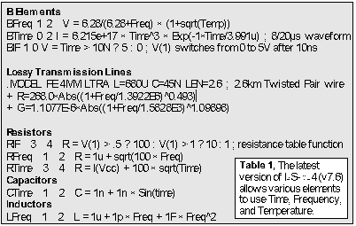
The B element offers a wide range of math operators including Abs, log, exp, signum, and trigonometric. Newly added functions to ISSPICE4 version 7.6 (due for release shortly) include modulo, ceiling, floor, fraction, integer, random number, max, and min.
Time, Temperature, and Frequency Expressions in ISSPICE4
With the next version of ISSPICE4, users will also be able
to specify “time” (transient analysis), “freq”
(frequency), or “temp”
(.Options TEMP function) as variables in the resistor, capacitor,
inductor, lossy transmission line and B elements. For passive
elements, the frequency variable will allow you to have a nonlinear
frequency dependence. The new variables may be combined with any
mathematical, If-Then-Else, and Boolean expression.
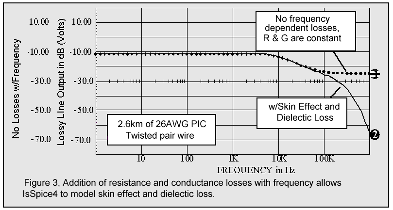
Figure 3 shows a simulation of the new lossy line model with and without frequency dependence in the resistor and conductance model parameters. The actual model statement is shown in Table 1. The frequency dependence adds skin effect and dielectric loss to the model. In order to further illustrate B element usage, two other articles on modeling MOVs and capacitors are provided in this newsletter.
ISSPICE4 is the ideal tool for analyzing both repeatable and
random transient events. It is especially effective in analyzing
events that can not be easily recreated in the laboratory. For
the study of protection devices, virtually any stimulus waveform
can be created and both attenuating (filters) and diverting devices
(crowbar-type devices) can be modeled. Fuses, for
example, were covered in a previous newsletter [1]. In this article,
we present a SPICE model for a MOV. Among other
things, the model permits calculation of the protection response
for different overvoltage waveshapes. Possible repeatable and
random applications include the study of transients on AC power
lines, transients from switch arcing, power faults, lighting strikes,
automotive transients such as “load dump”, alternator
field decay, and inductive switching.
A varistor functions as a nonlinear variable impedance. Its response can be approximated by the function I = KVa, as explained in [2, 3], where a represents the degree of nonlinearity. While this function can be modeled with SPICE 2G polynomials, unnecessary complexity results even for linear values of a. With the ISSPICE4 B element, we can reduce the complexity while allowing more accurate control of a..
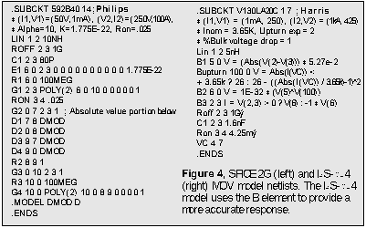
The SPICE2G and ISSPICE4 subcircuits are shown in Figure 4. A cascade of 2 sources is used in order to avoid problems with large K values. The subcircuit implements the following relationship: I = V(6) = K2(K1V)a = 1e-32 * K1Va with V(5) = |V(2,3)| * K1. The absolute value elements in SPICE 2 are replaced with the Abs function in B1. B3 keeps the current flowing in the proper direction. The model in [3] does not account for the upturn region at high voltages. It uses a constant value for a. This deficiency is corrected with the ISSPICE4 If-Then-Else expression feature. The output node, V(100), in the Bupturn statement in Figure 4, generates the nonlinear a value. When the current in the MOV reaches 3650A, a is reduced from its value of 26, thus causing the curve to bend upward. Roff and Ron represent the leakage and bulk resistance, respectively.
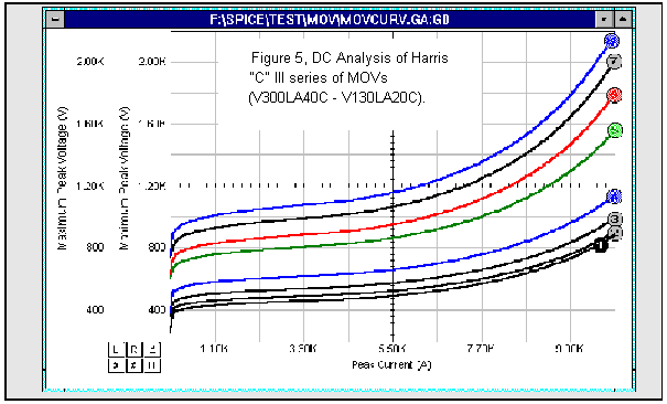
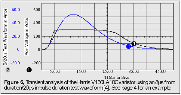
The graph in Figure 5 shows the nonlinear V-I response for several Harris MOVs, while Figure 6 shows the transient response to a 8/20us test waveform. Test waveshapes repre- sentative of surge voltages are available directly out of the ICAP/4 stimulus libraries; no development is required [4].
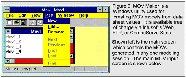
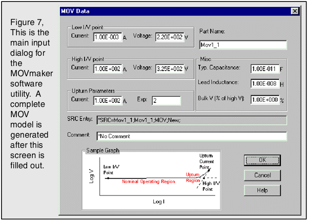
In order to ease the conversion of varistor data sheet param- eters into ISSPICE4 models, a software utility was created. To model a new part, you simply fill out the screen shown in Figure 7. Several models can be generated and edited in the same session. On-line help is provided to assist you in filing out the data screen and for reference material. Once completed, the models can be saved in an ASCII library file. The Windows program, MOVMaker.EXE, is available FREE of charge via Intusoft’s Web, FTP, or CompuServe sites. Over 200 models for Philips and Harris MOVs are included on the newsletter floppy disk for subscribers. On a related note, simulation of spark gaps devices will be covered in a future issue.
References
In addition to our popular forum on CompuServe, Intusoft has
added FTP and Web sites. The addresses are:
http://www.intusoft.com or ftp://ftp.intusoft.com.
A variety of software demos, modeling utilities, and SPICE
models are available FREE for viewing and downloading.
Other useful items include technical articles and application
notes on SPICE related topics and Intusoft Newsletters posted
electronically. Other forums that are in the works are:
Intusoft is committed to making its home page THE place to
go for information on SPICE, modeling, and analog/mixed signal
simulation related topics. Feel free to visit our page and leave
some suggestions on how we can better serve you.
BACK
TO THE TOP
Intusoft, in conjunction with Analytic Artistry™, is going to be releasing a NEW nonlinear magnetics design software package. The Magnetics Designer Series for Windows will consist of high performance programs for designing and analyzing various types of transformers, inductors, and chokes. The first program, the “Transformer/ Inductor Spreadsheet,” is an easy-to-use package that will allow you to design transformers and inductors from either electrical or geometrical specifications. The package will also produce a winding report that can be used for production purposes. Typical applications include: 60Hz power transformers using laminated El cores, 400Hz transformers using Cut-C cores, high frequency switching regulator power transformers using ferrite cores and various types of chokes. More information on the release of these programs will be available in the next Intusoft Newsletter.
For those interested in learning about analog simulators based
on Berkeley SPICE 2, Intusoft has a special book available. It’s
called “SIMULATING WITH SPICE” and it covers learning
and using the universally accepted version of SPICE 2G.6. It includes
a tutorial for novice users, a dozen examples with helpful hints,
and an advanced techniques section with several application notes.
A complete SPICE syntax reference guide with ex- amples is also
included. Best of all, this great reference book is available
for just $15 (plus $10 S&H, U.S.A.) while they last.
Intusoft Celebrates Its 10th Anniversary
Intusoft was founded in 1985 by Larry Meares. At the time,
Mr. Meares was looking for an affordable PC compatible SPICE
simulator. He couldn’t find one, so he created his own. ISSPICE
analog circuit simulation software was first introduced in September
1985. At an unprecedented price of $95 (amazingly, ISSPICE is
still priced at $95 in the U.S.), ISSPICE quickly became
a best seller, and sold over 800 copies by 1987.
Our R&D and technical support departments account for over
50% of our labor force. We have devoted ourselves to supplying
customers with the latest SPICE enhancements. Intusoft has long
been heralded as having the best SPICE technical support in the
industry. We are the only SPICE vendor to offer registered customers
a FREE modeling service. Unlike other vendors who farm out service
tasks, Intusoft also offers its own on-site SPICE training classes.
Over the past 8 years, hundreds of engineers have taken advantage
of Intusoft’s training seminars. Other tech. support services
include CompuServe and Internet sites where you can download
free models, application notes, and free SPICE software.
Over the years, our customers have come to trust Intusoft for
our cutting-edge technology as well as an unbeatable price/performance
ratio. August 1995 marked our ten year anniversary, and we shipped
our 14,000th SPICE package at that time. Ten years in the
software industry is no small achievement in the competitive EDA
world. How were we able to achieve a nearly 40% annual
growth over this 10 year period? We listened, researched, and
moved ahead of the pack. The Intusoft success is earmarked
by many unique characteristics:
Intusoft’s next 10 years will also be filled with many
firsts. If you have purchased software from us we thank you and
hope you’ll
continue to let us serve you. If not, then we invite you to see
just how much simulation power your money can buy.
In this edition of the modeling corner, we present models from Kemet Electronics Corp. and Intusoft Tech Support. The Intusoft Newsletter subscription disk contains new op-amp models from Comlinear and Apex, new Power Mosfet and IGBT models from Harris and Omnirel, plus over 200 varistor models created by Intusoft’s technical support staff. Also included are some realistic capacitor models which are described next.
Modeling a Capacitor
It may not be clear, especially to novice users, that when
you use a passive component, such as a resistor or capacitor,
you
are using an IDEAL element. NO parasitics, such as capacitor ESR
or inductor series resistance, are included. This is done
intentionally (to confuse you, not exactly, but sometimes it may
feel that way) to allow you to take advantage of the ideal nature
of these elements. However, parasitics can both dominate and plague
a circuit design. Therefore, good device models are an
essential part of a realistic simulation.
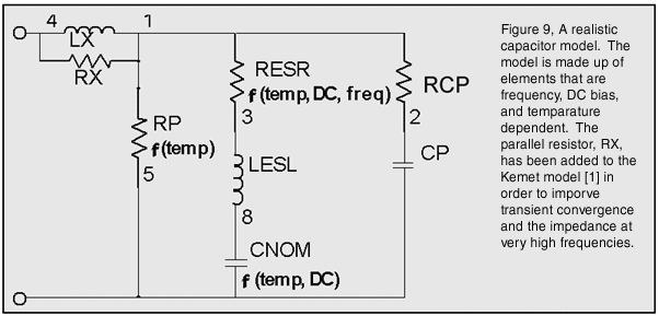
While it is common to represent a capacitor with a series R (ESR), L (ESL), and C (nominal capacitance) combination, a more realistic subcircuit representation of a ceramic capacitor is shown in Figure 9 [1].
The model is made up of an ESR (Resr) value that is frequency, DC bias, and temperature dependent. The capacitance (Cnom) is DC bias and temperature dependent. The parallel resistor, RP, is also temperature dependent. It represents the leakage or insulation resistance. RCP and CP create a secondary, or parallel, resonance that represents a capacitance that shunts the RLC elements. CP is dependent on the body and chip size. Lx is used to keep the parallel resonance in check and account for the pad/lead inductance.
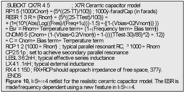
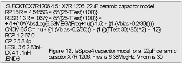
Referring to Figures 10, 11, and 12,
Rnom is the minimum resistance at self-resonance (Fres variable).
The self reso-
nance is widened out by the 1.5 factor in the frequency term.
This value was chosen as a best fit to actual data. The
frequency dependence was provided by inserting the “Freq”
term into the resistance expression. This is a new capability
for
the resistor element and results in a response that is frequency
dependent. During the AC analysis, Freq is set to the frequency
being simulated. For the transient analyses, the value of Freq
is set to zero, thus making the ESR large. The “R=”
is only
required when the resistance is re-evaluated during the simulation.
The expressions and variables in curly braces, { }, are
automatically evaluated before the simulation is run.
It should be noted that a ratio of Laplace polynomial expressions
may also be used in ISSPICE4. These “Laplace blocks”
will
have both an AC and a transient response and can be used to derive
virtually any linear transfer function of s.
Ttest is the temperature of the capacitor. It may also be set
to the keyword “TEMP” (= .Options Temp value). Vbias
is the DC bias applied to the capacitor. Vnom is the voltage at
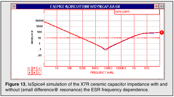
which the capacitance drops by 20%. This ability to use the “Freq”,
“Temp” or “Time” variables is not yet available
in ISSPICE4, but will be in the next version (v7.6). This version
was used to generate the response in
Figure 13.
The required capacitor related values may be obtained from
your capacitor manufacturer. Kemet Electronics Corp. (P.O. Box
5928, Greenville, SC 29606, (803) 963-6300) was responsible for
the information supplied to Intusoft (Thanks to J. Prymak @ Kemet).
Reference
[1] provides further derivation of, and reasoning behind, the equations in Figure 10. It also provides equations for NP0, C0G, and Y5V capacitor families. SPICE models were not provided in [1] due to syntactical issues. The new ISSPICE4 B element alleviates these roadblocks. Several models for the X7R, C0G, and NP0 families of capacitors are available on the Intusoft Web site with the complete SPICE offering on the newsletter subscribers disk. In the next Intusoft Newsletter we will derive a realistic model for a tantalum capacitor.
[1] “SPICE Modeling of Capacitors”, John Prymak, CARTS 95: 15th Capacitor and Resistor Technology Sym., March 1995
Copyright ©2002 Intusoft, All Rights Reserved